Refer to fig. 7-12 or fig. 7-13. pin 6 of the 7432 ic g... 11: circuit 74283 -gate level Solved 1. the attached file shows the data sheet for chip
SOLVED: The circuit to be constructed implements a 4-bit Adder
74283 ic circuit diagram
Cd4008 4-bit full adder ic pinout, working, example and datasheet
74283 ic circuit diagram7432 ic circuit diagram [solved]: 2. use the ic 74283 or 7483 to add the given numb4-bit binary full adder pdip-16 type sn74283n, grieder elektronik.
Ls bit full adder ic pinout proteus examples applicationsBinary full adder 4 bit 74283 Solved 1. a. explain how the ic 74283 works as a subtractor.Circuit diagram for 4 bit binary adder using ic 7483.

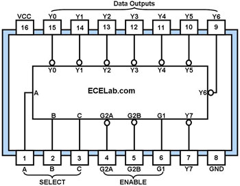
74ls138 ic : pin diagram, circuit, and applications
Adder bit proteus ic datasheet microcontrollerslabSumador bits integrado diagrama circuito montaje Ic fig refer solution goes wiring diagram[diagram] 1 of 8 decoder logic diagram.
74ls283 4-bit binary full add with fast carryLogic gates electric schematic diagram 74283 ic price in bdCircuit design 4 bit parallel adder subtractor using ic 74283.

Solved: the circuit to be constructed implements a 4-bit adder
Solved: draw a diagram of a four-bit binary adder/subtractor (assuming74283 ic price in bd Sumador 4 bits con integrado 7428374283 datasheet(pdf).
Ic 7483 internal circuit diagramSolved problem 1. adder ic (74ls283) the circuit diagram and Decoder circuit ic datasheet diagram pinout chip line logic high gates components ttl data transmission decoding output led components101 circuitry74283 ic circuit diagram.

74283 ic circuit diagram
74hc83 full adder ic pinout datasheet equivalent and working3 bit comparator circuit diagram The logic diagram shown below implements the first stage of an ic ship74283 ic 4-bit binary adder.
Solved question 1: adder ic (74ls283) the circuit diagram74138 circuit diagram 74ls138 decoder pinout, features, circuit & datasheet.
![[Solved]: 2. Use the IC 74283 or 7483 to add the given numb](https://i2.wp.com/media.cheggcdn.com/study/ad7/ad782ed9-7ffa-46a3-b61d-847d979f4150/image)